- Bộ lập trình PLC, cáp lập trình
- Màn hình HMI
- Cảm biến, phụ kiện
- Biến tần, khởi động mềm
- Máy cắt, Aptomat, khởi động từ
- Thiết bị đo lường, bảo vệ
- Thiết bị công nghiệp, tự động hóa
- Thủy lực, khí nén, van công nghiệp
- Motor, Servo motor, Servo Amplifier
- Thyristor, Module, SCR, SSR, Diode
- Phụ kiện tủ điện và vỏ tủ điện
- Cáp điện, ống bảo vệ cáp
- Thiết bị điện trung thế, truyền tải
- Thiết bị chống sét, kim thu sét
- Dụng cụ cầm tay, dụng cụ tool
- ATS, UPS, tụ bù, cuộn kháng
-
Thiết bị ngành xi măng, thép, nhiệt điện
-
Thiết bị vật tư điện nhẹ-viễn thông
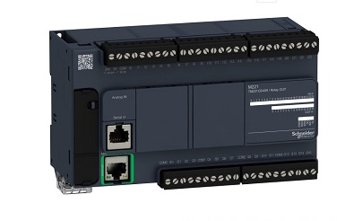
Bộ điều khiển lập trình Schneider PLC Modicon TM241 TM241CEC24R TM241CEC24T TM241CEC24U TM241CE40R TM241CE40T TM241CE40U TM241C40R TM241C40T TM241C40U TM241CE24R TM241CE24T TM241CE24U TM241C80RPAC TM241C80TPAC TM241C80UPAC
Tình trạng sản phẩm:
Product Features
| Product Series | Modicon M241 | |
| product type | Programmable Controllers | |
| Rated power supply voltage [Us] | 100...240 V AC | |
| Discrete input quantity | 14 Discrete inputs include 8 fast inputs in accordance with IEC 61131-2 Type 1 | |
| Solid state output type | Transistor relay | |
| Discrete output quantity | 6 Relays 4 Transistors include 4 fast outputs | |
| Discrete output voltage | Transistor output for 24 V DC 5...125 V Relay output for DC 5...250 V Relay output for AC | |
| Discrete output current | 2 A and Q4...Q9 terminals are suitable for relay output 0.1 A and TR0...TR3 terminals are suitable for fast output (PTO mode) 0.5 A and TR0...TR3 terminals are suitable for transistor output |
| Discrete I/O number | twenty four | |
| Number of I/O expansion modules | 7 (Local I/O system) 14 (Remote I/O system) | |
| Power supply voltage range | 85...264 V | |
| Network frequency | 50/60 Hz | |
| Discrete input logic | Sink or source | |
| Discrete input voltage | 24 V | |
| Discrete input voltage type | Direct current | |
| Voltage state 1 guarantee | >= 15 V applicable input | |
| Voltage state 0 guarantee | <= 5 V applicable input | |
| Discrete input current | 5 mA applicable input | |
| input resistance | 4.7 kOhm applicable input | |
| Response time | 50 &icro;s open operation and I0...I13 terminal applicable input | |
| Configurable filter time | 1 &icro;s for fast input | |
| Discrete output logic | Positive logic (source) | |
| Output voltage limit | 125 V DC relay output 30 V DC transistor output 277 V AC relay output | |
| Output frequency | <= 1 kHz for transistor output <= 20 kHz for fast output (PWM mode) <= 100 kHz for fast output (PLS mode) | |
| Precision | +/- 0.1% at 0.02...0.1 kHz for fast output +/- 1% at 0.1...1 kHz for fast output | |
| Type of protection | Short-circuit protection applies to transistor output . Short-circuit and overload protection with automatic reset applies to transistor output. Reverse phase protection applies to transistor output. No protection applies to relay output. | |
| Reset time | 10 ms automatic reset output 12 s automatic reset fast output | |
| storage | 8 MB applicable program 64 MB applicable system memory RAM | |
| data backup | 128 MB built-in flash memory for backup of user programs | |
| Data storage device | <= 32 GB SD card optional | |
| Battery Type | BR2033 lithium non-rechargeable, battery life: 4 years | |
| Cumulative running time | 2 years at 25 °C | |
| 1K instruction execution time | 0.3 ms for events and periodic tasks 0.7 ms for other instructions | |
| Application structure | 8 Item 3 cyclic main task + 1 flywheel task 4 cyclic main task 8 external event tasks | |
| Real Time Clock | Have | |
| Clock error | <= 60 s/month at 25 °C | |
| GPS | PTO function 4 channels (positioning frequency: 100 kHz) | |
| Calculate the number of inputs | 4 Fast input (high count mode) at 200 kHz 14 Standard input at 1 kHz | |
| Control signal type | A/B signal at 100 kHz for fast input (high count mode) pulse/direction signal at 200 kHz for fast input (high count mode) single-phase signal at 200 kHz for fast input (high count Counting mode) | |
| Integrated connection type | USB port with connector mini B USB 2.0 Ethernet with connector RJ45 non-isolated serial link "serial 1" with connector RJ45 and interface RS232/RS485 non-isolated serial link "serial 2" with use Detachable screw terminal and interface RS485 CANopen J1939 for use with connector pin type SUB-D 9 | |
| power supply | Serial link power supply "Serial 1" at 5 V, 200 mA | |
| Transfer rate | 1.2...115.2 kbit/s (default 115.2 kbit/s) for bus length... 15 m-communication protocol: RS485 1.2...115.2 kbit/s (default 115.2 kbit/s) for bus length... 3 m-Communication protocol: RS232 480 Mbit/s for a bus length of… 3 m-communication protocol: USB 10/100 Mbit/s-Communication protocol: Ethernet 1000 kbit/s for a bus length of… 20 m-Communication protocol : CANopen 800 kbit/s for bus length… 40 m-communication protocol: CANopen 500 kbit/s for bus length… 100 m-communication protocol: CANopen 250 kbit/s for bus length… 250 m-communication Protocol: CANopen 125 kbit/s for bus length… 500 m-Communication protocol: CANopen 50 kbit/s for bus length… 1000 m-Communication protocol: CANopen 20 kbit/s for bus length… 2500 m- Communication protocol: CANopen | |
| Protocol | Modbus non-isolated serial link and master/slave issues | |
| Ethernet port | 1-10BASE-T/100BASE-TX port and copper cable support | |
| Communication service | Ehternet/IP converter DHCP client IEC VAR ACCESS Modbus TCP client Modbus TCP server Modbus TCP slave device SNMP client/server FTP client/server SQL client Send and receive email from the controller based on TCP/UDP library Web server (WebVisu & XWeb system ) OPC UA server DNS client | |
| Local signal | 1 LED green for SD card (SD) 1 LED red for BAT 1 LED green for SL1 1 LED green for SL2 per channel 1 LED green for I/O status 1 LED red for I/O error (I/O) 1 LED red for bus fault on TM4 (TM4) 1 LED green for Ethernet port activity 1 LED green for CANopen operation 1 LED green for CANopen error 1 LED red for module error (ERR) 1 LED green for PWR 1 LED green for RUN | |
| Electrical connections | Removable screw terminal for input and output (5.08mm tilt) Removable screw terminal for connection to 24 V DC power supply (5.08mm tilt) | |
| max cable distance between devices | Shielded cable: 10 m for fast input Shielded cable: 3 m for fast output Unshielded cable: 50 m for input Unshielded cable: 50 m for output | |
| isolation | Non-insulated between supply and ground between 500 V AC power supply and internal logic | |
| Logo | CE | |
| Sensor power supply | 24 V DC at 400 mA supplied by the controller | |
| Surge tolerance | 2 kV applicable power line (AC) internal common mode conforms to EN/IEC 61000-4-5 2 kV applicable relay output internal common mode conforms to EN/IEC 61000-4-5 1 kV applicable shielded cable internal common mode conforms to EN/IEC 61000 -4-5 1 kV Applicable power line (AC) internal differential mode conforms to EN/IEC 61000-4-5 1 kV Applicable relay output internal differential mode conforms to EN/IEC 61000-4-5 1 kV Applicable input internal common mode conforms to EN /IEC 61000-4-5 1 kV applicable transistor output common mode conforms to EN/IEC 61000-4-5 | |
| Web service | Network Server | |
| Number of connections | 16 Connection) Applicable Ethernet/IP device 8) Applicable Modbus server | |
| CANopen feature profile | DS 301 V4.02 DR 303-1 | |
| Number of slaves | <= 63 CANopen | |
| Installation method | Top hat type TH35-15 Rail installation conforms to IEC 60715 Top hat type TH35-7.5 Rail installation conforms to IEC 60715 board or board with fixing kit | |
| high | 90 mm | |
| depth | 95 mm | |
| width | 150 mm | |
| product weight | 0.53 kg |
| standard | CSA C22.2 No 142 ANSI/ISA 12-12-01 UL 1604 CSA C22.2 No 213 EN/IEC 61131-2: 2007 Marine Technical Index (LR, ABS, DNV, GL) UL 508 | |
| certified product | cULus CSA IACS E10 RCM | |
| Anti-static discharge | 4 kV contact in accordance with EN/IEC 61000-4-2 8 kV in air in accordance with EN/IEC 61000-4-2 | |
| Anti-electromagnetic domain | 10 V/m (80 MHz...1 GHz) conforms to EN/IEC 61000-4-3 3 V/m (1.4 GHz-2 GHz) conforms to EN/IEC 61000-4-3 1 V/m (2 GHz. ..3 GHz) Conforms to EN/IEC 61000-4-3 | |
| Ability to resist instantaneous pulse | 2 kV applicable power line conforms to EN/IEC 61000-4-4 2 kV applicable relay output conforms to EN/IEC 61000-4-4 1 kV applicable Ethernet line conforms to EN/IEC 61000-4-4 1 kV applicable serial link conforms to EN /IEC 61000-4-4 1 kV applicable input conforms to EN/IEC 61000-4-4 1 kV applicable transistor output conforms to EN/IEC 61000-4-4 | |
| Conducted interference resistance | 10 V (0.15...80 MHz) conforms to EN/IEC 61000-4-6 3 V (0.1...80 MHz) conforms to marine specifications (LR, ABS, DNV, GL) 10 V (calibration frequency (2, 3 , 4, 6.2, 8.2, 12.6, 16.5, 18.8, 22, 25 MHz)) in line with marine specifications (LR, ABS, DNV, GL) | |
| Electromagnetic radiation | Conducted emission, test level: 120...69 dB&icro;V/m QP, condition test: power line radio frequency: 10...150 kHz) Conforms to EN/IEC 55011 conducted emission, test level: 63 dB&u;V/m QP , Conditional test: power line radio frequency: 1.5...30 MHz) Conforms to EN/IEC 55011 conducted emission, test level: 79 dB&u;V/m QP/66 dB&u;V/m AV, conditional test: power line radio frequency: 0.15 ...0.5 MHz) in accordance with EN/IEC 55011 conducted emission, test level: 73 dB&u;V/m QP/60 dB&u;V/m AV, condition test: power line radio frequency: 0.5...300 MHz) in accordance with EN/ IEC 55011 radiated emissions, test level: 40 dB&u;V/m QP and Class A, condition test: 10 m RF: 30...230 MHz) Compliance with EN/IEC 55011 Conducted emissions, test level: 79...63 dB&u ;V/m QP, condition of test: power lines (radio frequency: 150...1500 kHz) conforming to EN/IEC 55011 Radiated emissions, test level: 47 dB&u;V/m QP with class A, condition of test: 10 m (radio frequency: 230...1000 MHz) conforming to EN/IEC 55011 | |
| Resistance to instantaneous power failure | 10 ms | |
| Ambient temperature | -10...55 °C for vertical installation -10...50 °C for vertical installation | |
| Storage temperature | -25...70 °C | |
| Relative humidity | 10...95% during non-condensing operation 10...95% during non-condensing storage | |
| IP protection level | IP20 protective cover in place | |
| Pollution level | 2 | |
| Working altitude | 0...2000 m | |
| Storage height | 0...3000 m | |
| Anti-vibration | 3.5 mm vibration frequency: 5...8.4 Hz) on the uniform rail 3 gn vibration frequency: 8.4...150 Hz) on the uniform rail 3.5 mm vibration frequency: 5...8.4 Hz) on the upper panel Installation 3 gn Vibration frequency: 8.4...150 Hz) Installation on the upper panel | |
| Impact resistance | 15 gn for 11 ms |
| product type | Green product certification mark (Green Premium) products | |
| RoHS regulations (date code: YYWW) | Conformity-Since the 50th week of 2013-Schneider Electric declaration of conformity ::%d">Schneider Electric declaration of conformity | |
| REACh regulations | ::%d">The content of toxic and hazardous substances is below the limit required by REACH | |
| Environmental compliance | provide support | |
| Recycling guide | provide support |
-
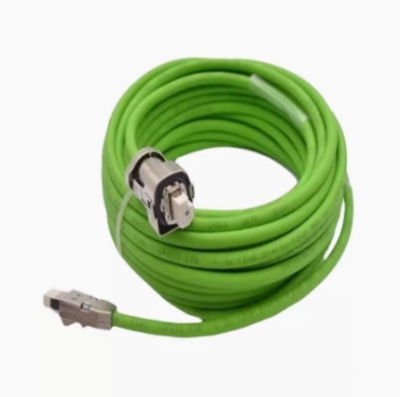
- Cáp nguồn, cáp tín hiệu Siemens servo power line and signal line 6FX5002-2DC10-1AB0 6FX5002-5CN01-1AB0 6FX5002-2CF02-1AB0 6FX5002-2DC00-1AB0 Liên hệ
-
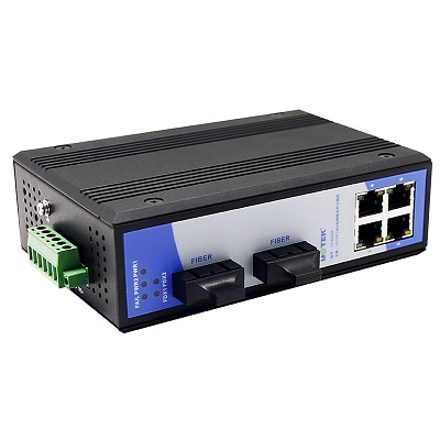
- Mô đun truyền thông UTEK 6-port single-mode 2 optical 4 electrical industrial Ethernet switch 100M rail UT-62204SM/MM Liên hệ
-
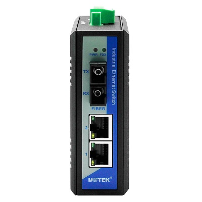
- Mô đun truyền thông UTEK industrial grade 1 optical 2 electrical switch fiber optic transceiver SC interface UT-60-D2T1SC Liên hệ
-
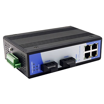
- Mô đun truyền thông 6-port single-mode 2 optical 4 electrical industrial Ethernet switch 100M rail UT-62204SM/MM Liên hệ
-
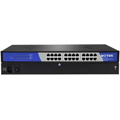
- Mô đun truyền thông UTEK 24-port rack-mounted 100M industrial Ethernet switch unmanaged UT-6524 Liên hệ
-
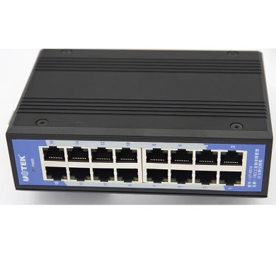
- Mô đun truyền thông UTEK industrial-grade Ethernet switch 16-port rail-type network monitoring UT-6516 Liên hệ
-
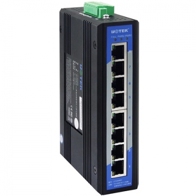
- Mô đun truyền thông UTEK 100M 8-port industrial Ethernet switch 100M rail-type unmanaged UT-6408 Liên hệ
-
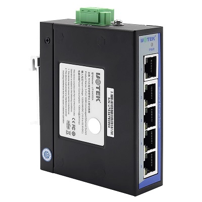
- Mô đun truyền thông UTEK industrial grade 5-port 100M unmanaged Ethernet switch rail anti-static surge UT-6405SA Liên hệ
-
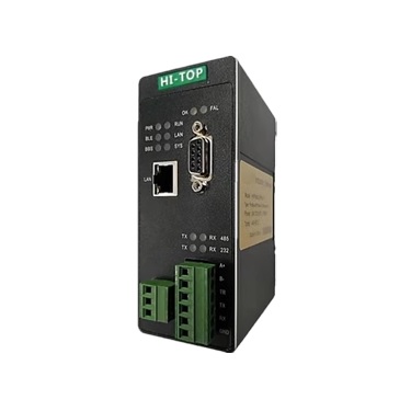
- Mô đun truyền thông HI-TOP PROFIBUS DP master station communication management machine to MODBUS RTU/TCP slave station protocol converter gateway Liên hệ
-
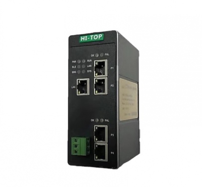
- Mô đun truyền thông HI-TOP HI-TOP EtherNet/IP to Profinet protocol conversion gateway industrial grade HT3S-PNS-EIS Liên hệ
-

- Mô đun truyền thông HI-TOP Profinet to EtherCAT gateway HT3S-PNS-ECS supports robot conversion to Siemens PLC Liên hệ
-
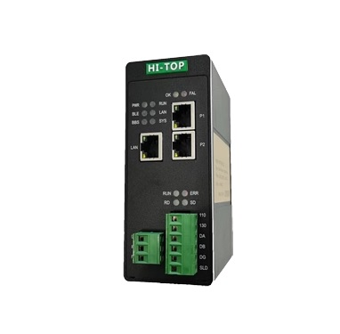
- Mô đun truyền thông HI-TOP Modbus RTU/TCP to EtherCAT protocol converter gateway HT3S-ECS-MDN Liên hệ
TÂN THÀNH CAM KẾT
- Sản phẩm, hàng hóa chính hãng.
- Giá cả cạnh tranh.
- Dịch vụ chăm sóc khách hàng tận tâm.
Thông Tin Công Ty
Chính sách và quy định
Hỗ trợ khách hàng
THÔNG TIN LIÊN HỆ:
-------------------------------
CÔNG TY TNHH THIẾT BỊ CÔNG NGHIỆP TTH
Trụ sở: số 124 ngõ 79 Yên Hoà-Cầu giấy-HN
Kinh doanh 1 : 0816.861.515
Kinh doanh 2 : 0836.861.515
Email: tthkinhdoanh@gmail.com
Email: tthkinhdoanh01@gmail.com

