- Bộ lập trình PLC, cáp lập trình
- Màn hình HMI
- Cảm biến, phụ kiện
- Biến tần, khởi động mềm
- Máy cắt, Aptomat, khởi động từ
- Thiết bị đo lường, bảo vệ
- Thiết bị công nghiệp, tự động hóa
- Thủy lực, khí nén, van công nghiệp
- Motor, Servo motor, Servo Amplifier
- Thyristor, Module, SCR, SSR, Diode
- Phụ kiện tủ điện và vỏ tủ điện
- Cáp điện, ống bảo vệ cáp
- Thiết bị điện trung thế, truyền tải
- Thiết bị chống sét, kim thu sét
- Dụng cụ cầm tay, dụng cụ tool
- ATS, UPS, tụ bù, cuộn kháng
-
Thiết bị ngành xi măng, thép, nhiệt điện
-
Thiết bị vật tư điện nhẹ-viễn thông
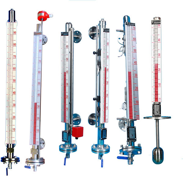
Thiết bị đo mức kiểu từ tính, Magnetic flap level gauge, Magnetic float level gauge Raylink UHZ-10
Thiết bị đo mức kiểu từ tính, Magnetic flap level gauge, Magnetic float level gauge Raylink UHZ-10
Tình trạng sản phẩm:
The side-mounted magnetic flap liquid level gauge produced by Suzhou Leining Automation Instrumentation Co., Ltd. is used in various environments such as low temperature to high temperature, vacuum to high pressure, etc. It is an ideal liquid level measurement product for petroleum, chemical and other industrial sectors. According to the different installation positions in the container, side loading and top loading are available. According to different working media, three materials are provided: stainless steel, ABS and PP-R engineering plastics, of which ABS and PP-R materials are suitable for corrosive media such as acid and alkali.
The detailed information of the side-mounted magnetic flap level gauge:
1. The float is used as the measuring element, and the magnetic steel drives the turning column display, no energy is required.
2. Equipped with upper and lower limit switch output, it can realize remote alarm and limit control.
3. Equipped with a transmitter to realize liquid level remote report indication, detection and control.
| Structure and working principle of side-mounted magnetic flap level gauge |
1 , basic
buoyancy principle, lifting of the float with the level in the measuring tube and the upper and lower movement of the permanent magnet in the float through the coupling, the driving red, white turned column flipped 180 °, the column turned from the liquid level rises From white to red, from red to white when descending, so as to achieve liquid level indication.
2. Electric remote transmission
installs a transmitter on the float level gauge. The float moves up and down, and the measurement elements in the guide rod are sequentially operated by the magnetic coupling action to obtain the change of the resistance signal, which is converted into a standard of 0-10mA or 4-20mA The signal output is connected with the display instrument or computer to achieve the purpose of remote transmission.
3. The upper and lower limit switch output
is set by the user on the upper and lower limit positions of the level gauge. The controller is equipped with a self-retaining reed switch. The magnetic float is used to move the reed switch with the liquid level. At the time, realize the alarm or limit control.
System composition and wiring
1. The upper and lower limit switch outputs are
composed of self-holding reed switches and converters. The reed switches and converters are installed in the field and the control room, respectively. The converter provides three pairs of contact switches.
2. Electric remote transmission
consists of two parts: measuring unit and transmission unit.
3. Intrinsically safe explosion-proof
a With intrinsically safe explosion-proof, the upper and lower limit switch output type
explosion - proof switches are composed of reed switches and safety barriers with relay contacts, which can directly provide users with a pair of normally open or normally closed contacts. If users need more contacts, they can be specially designed and ordered. (Picture 3)
b The intrinsically safe explosion-proof remote transmission type is
suitable for Class ∏ electrical equipment (for factory use), Class C gas, and the highest surface temperature group T4 (135 ° C). (Figure 4)
c Precautions for use
① The outer shell of the transmitter is provided with an external ground, and the user must be reliably grounded when using it.
② The use of safety barriers should comply with the relevant instructions.
③The connecting cable between the transmitter and the intrinsic safety end of the safety barrier is a two-core shielded cable, the core wire cross-sectional area is> 0.5m, and the allowable distributed capacitance of the cable is 0.8μF.

| User-supplied flange | ||||||||||||||||||||||||||||||||||||||||||||||||||||||||||||||
| ||||||||||||||||||||||||||||||||||||||||||||||||||||||||||||||
| Main Specifications | ||||||||||||||||||||||||||||||||||||||||||||||||||||||||||||||
| ||||||||||||||||||||||||||||||||||||||||||||||||||||||||||||||
| Model Description | ||||||||||||||||||||||||||||||||||||||||||||||||||||||||||||||
| ||||||||||||||||||||||||||||||||||||||||||||||||||||||||||||||
TÂN THÀNH CAM KẾT
- Sản phẩm, hàng hóa chính hãng.
- Giá cả cạnh tranh.
- Dịch vụ chăm sóc khách hàng tận tâm.
Thông Tin Công Ty
Chính sách và quy định
Đã thông báo

Hỗ trợ khách hàng
THÔNG TIN LIÊN HỆ:
-------------------------------
CÔNG TY TNHH THIẾT BỊ CÔNG NGHIỆP TTH
Trụ sở: số 124 ngõ 79 Yên Hoà-Cầu giấy-HN
Kinh doanh 1 : 0816.861.515
Kinh doanh 2 : 0836.861.515
Email: tthkinhdoanh@gmail.com
Email: tthkinhdoanh01@gmail.com
