- Bộ lập trình PLC, cáp lập trình
- Màn hình HMI
- Cảm biến, phụ kiện
- Biến tần, khởi động mềm
- Máy cắt, Aptomat, khởi động từ
- Thiết bị đo lường, bảo vệ
- Thiết bị công nghiệp, tự động hóa
- Thủy lực, khí nén, van công nghiệp
- Motor, Servo motor, Servo Amplifier
- Thyristor, Module, SCR, SSR, Diode
- Phụ kiện tủ điện và vỏ tủ điện
- Cáp điện, ống bảo vệ cáp
- Thiết bị điện trung thế, truyền tải
- Thiết bị chống sét, kim thu sét
- Dụng cụ cầm tay, dụng cụ tool
- ATS, UPS, tụ bù, cuộn kháng
-
Thiết bị ngành xi măng, thép, nhiệt điện
-
Thiết bị vật tư điện nhẹ-viễn thông
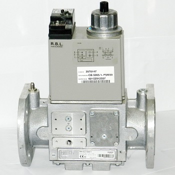
DMV-D5065/11 DMV-DLE5065/11 eco DUNGS | Gas Solenoid Valve | Combination Valve
Tình trạng sản phẩm:
| Product Description: | |||||||||||||||||||||||||||||||||||||||||||||||||||||||||||||||||||||||||||||||||||||||||||||||||||||||||||||||||||||||||||||||||
|
-
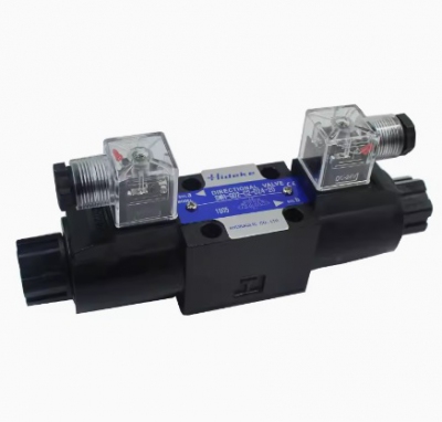
- Van thủy lực HIDEKE SWH-G02-C2-10 SWH-G02-C3-10 SWH-G02-C4-10 SWH-G02-C5-10 SWH-G02-C6-10 SWH-G02-C7-10 SWH-G02-C9-10 SWH-G02-D2-10 SWH-G02-C2-20 SWH-G02-C3-20 SWH-G02-C4-20 SWH-G02-C5-20 SWH-G02-C6-20 SWH-G02-C7-20 SWH-G02-C9-20 SWH-G02-D2-20 Liên hệ
-
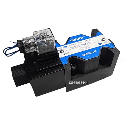
- Van thủy lực Risuny D5-03-2B2-A25 D5-03-2B2-D2 D5-03-2B2L-A25 D5-03-2B2L-D2 D5-03-2B2B-A25 D5-03-2B2B-D2 D5-03-2B3B-A25 D5-03-2B3B-L-A25 D5-03-2B3B-D2 D5-03-2B3-A25 D5-03-2B3-D2 D5-03-2B2A-A25 D5-03-2B2A-D2 D5-03-2B3A-A25 D5-03-2B3A-D2 D5-03-2B8-A25 D5-03 Liên hệ
-
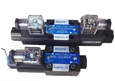
- Van thủy lực Risuny D5-02-3C2-D2 D5-02-3C2-A25-R D5-02-3C60-D2 D5-02-3C60-A25-R D5-02-3C3-D2 D5-02-3C3-A25-R D5-02-3C4-D2 D5-02-3C4-A25-R D5-02-3C5-D2 D5-02-3C5-A-25-R D5-02-2D2-D2 D5-02-2D2-A25-R D5-02-3C10-D2 D5-02-3C10-A25-R D5-02-3C9-D2 D5-02-3C9-A25- Liên hệ
-
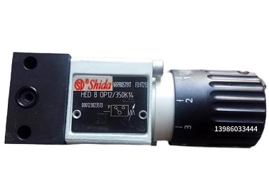
- Công tắc áp lực Shida pressure relay HED80A1X/50L24KW HED80A1X/100L24KW HED80A1X/200L24KW HED80A1X/350L24KW HED80A1X/50L220KW HED80A1X/100L220KW HED80A1X/200L220KW HED80A1X/350L220KW HED80A1X/ Liên hệ
-
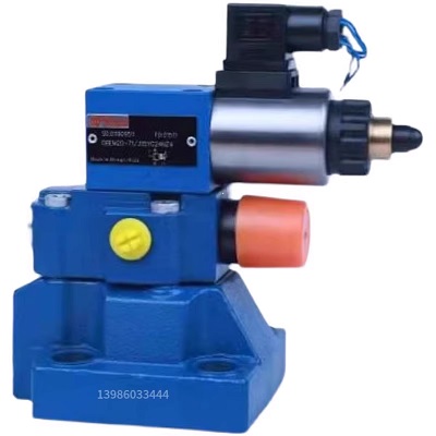
- Van thủy lực Shida DBEM10-71/50YG24K4M DBEM10-71/100YG24K4M DBEM10-71/200YG24K4M DBEM10-71/315YG24K4M DBEM10-70/50YG24K4M DBEM10-70/100YG24K4M DBEM10-70/200YG24K4M DBEM10-70/315YG24K4M DBEM10-7X Liên hệ
-
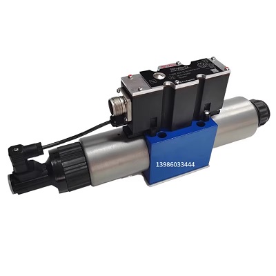
- Van thủy lực Shida 4WREE10E3-50-22/G24K31/A1V 4WREE10E50-22/G24K31/A1V-655 4WREE10E50-2X/G24K31/A1V 4WREE10E75-20/G24K31/A1V 4WREE10E1-75-2X/G24K31/A1V 4WREE10W75-22/G24K31 Liên hệ
-
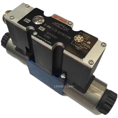
- Van thủy lực Shida 4WRAE10E60-22/G24K31/F1V 4WRAE10E60-2X/G24N9K31/A1M 4WRAE10E30-2X/G24K31/F1V 4WRAE10E30-2X/G24N9K31/A1M 4WRAE10E1-60-2X/G24K31/F1V 4WRAE10E1-60-2X/G24N9K31 Liên hệ
-
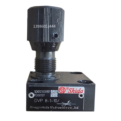
- Van thủy lực Shida DVP6-1-10/ DVP8-1-10/ DVP10-1-10/ DVP12-1-10/ DVP16-1-10/ DVP20-1-10/ DV6-1-10/2 DV8-1-10/2 DV10-1-10/2 DV12-1-10/2 DV16-1-10/2 DV20-1-10/2 Liên hệ
-
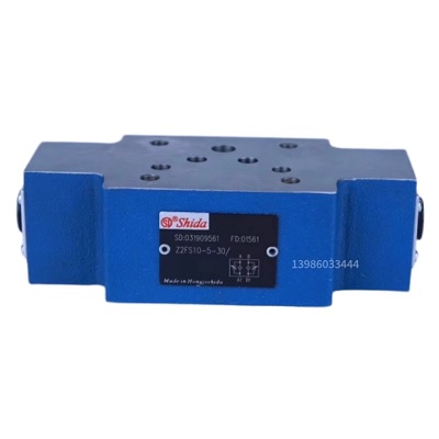
- Van thủy lực Shida Z2FS6-30 Z2FS6-30/S Z2FS6-30/S2 Z2FS6-2-40/2QV Z2FS6-2-40/2Q Z2FS6-2-40/1QV Z2FS6-2-40/1Q Z2FS6-2-4X Z2FS6-2-4X/S2 Z2FS6-5-40/2QV Z2FS6-5-40/2Q Z2FS10-20 Z2FS10-20/S Liên hệ
-
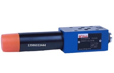
- Van thủy lực Shida ZDR6DP2-40/25YM ZDR6DP2-40/75YM ZDR6DP2-40/150YM ZDR6DP2-40/210YM ZDR6DA2-40/25YM ZDR6DA2-40/75YM ZDR6DA2-40/150YM ZDR6DA2-40/210YM ZDR6DB2-40/25YM ZDR6DB2-40/75YM Liên hệ
-
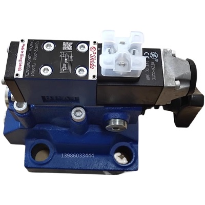
- Van thủy lực Shida DAW10B-1-30B/80G24NZ5L DAW10B-1-30B/160G24NZ5L DAW10B-1-30B/315G24NZ5L DAW10B-1-30B/80W220-50NZ5L DAW10B-1-30B/160W220-50NZ5L DAW10B-1-30B/315W220-50NZ5L DAW10B-2-30B/80G24NZ5L DAW10B-2-3 Liên hệ
-
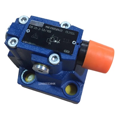
- Van thủy lực Shida DB10-2-5X/50 DB10-2-5X/100 DB10-2-5X/200 DB10-2-5X/315 DB10-2-5X/350 DB10-2-52/50 DB10-2-52/100 DB10-2-52/200 DB10-2-52/315 DB10-2-52/350 DB20-2-5X/50 DB20-2-5 Liên hệ
-
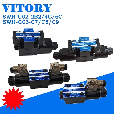
- Van điện từ Vitory SWH-G02-B2-10-DC24V SWH-G02-C2-20-AC220 SWH-G03-2B2-10-DC24V SWH-G03-C6-20-DC24V Liên hệ
-
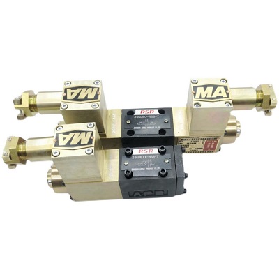
- van thủy lực kiểu phòng nổ Three-position four-way explosion-proof electromagnetic reversing valve 34GDEO-H6B-T 34GDBO/EY/H/EM/BM-H6B-T Liên hệ
-
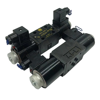
- van thủy lực, JIE&MING Hydraulic electromagnetic reversing valve 34BO-H6B-T/34EH-F6B-T/24EO-H6B/34BY/EM hydraulic system Liên hệ
TÂN THÀNH CAM KẾT
- Sản phẩm, hàng hóa chính hãng.
- Giá cả cạnh tranh.
- Dịch vụ chăm sóc khách hàng tận tâm.
Thông Tin Công Ty
Chính sách và quy định
Hỗ trợ khách hàng
THÔNG TIN LIÊN HỆ:
-------------------------------
CÔNG TY TNHH THIẾT BỊ CÔNG NGHIỆP TTH
Trụ sở: số 124 ngõ 79 Yên Hoà-Cầu giấy-HN
Kinh doanh 1 : 0816.861.515
Kinh doanh 2 : 0836.861.515
Email: tthkinhdoanh@gmail.com
Email: tthkinhdoanh01@gmail.com

