- Bộ lập trình PLC, cáp lập trình
- Màn hình HMI
- Cảm biến, phụ kiện
- Biến tần, khởi động mềm
- Máy cắt, Aptomat, khởi động từ
- Thiết bị đo lường, bảo vệ
- Thiết bị công nghiệp, tự động hóa
- Thủy lực, khí nén, van công nghiệp
- Motor, Servo motor, Servo Amplifier
- Thyristor, Module, SCR, SSR, Diode
- Phụ kiện tủ điện và vỏ tủ điện
- Cáp điện, ống bảo vệ cáp
- Thiết bị điện trung thế, truyền tải
- Thiết bị chống sét, kim thu sét
- Dụng cụ cầm tay, dụng cụ tool
- ATS, UPS, tụ bù, cuộn kháng
-
Thiết bị ngành xi măng, thép, nhiệt điện
-
Thiết bị vật tư điện nhẹ-viễn thông
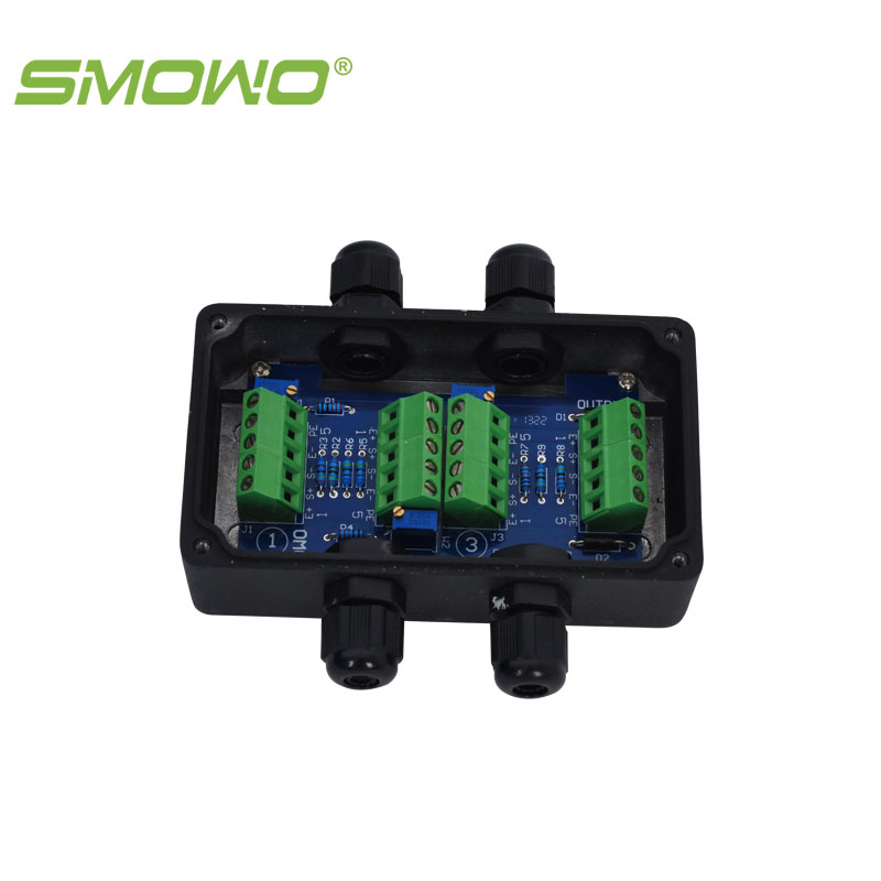
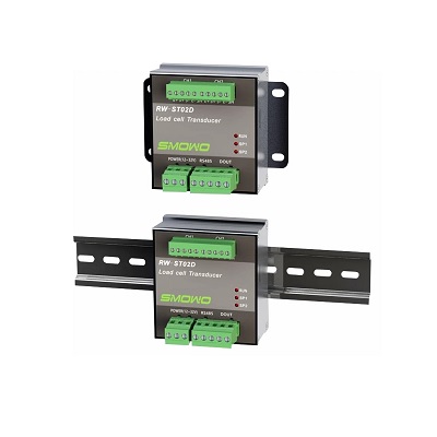
Hộp cầu đấu tín hiệu load cell 3 kênh SMOWO RW-JX03A
Hộp cầu đấu tín hiệu load cell 3 kênh SMOWO RW-JX03A
Tình trạng sản phẩm:
Sensor input wiring method (face to the terminal, from left to right , the wiring holes ① ~ ⑤)
| Terminal | 1 | 2 | 3 | 4 | 5 |
| definition | Sensor excitation positive | Sensor signal is positive | Sensor signal negative | Sensor excitation negative | shield |
| colour | Red | green | White | black | Rough black |
Note: The above wiring colors are only for sensors produced by our company .
Signal output wiring method (face to the terminal, from left to right , the wiring holes ① ~ ⑤)
| Terminal | 1 | 2 | 3 | 4 | 5 |
| definition | Sensor excitation positive | Sensor signal is positive | Sensor signal negative | Sensor excitation negative | shield |
| colour | Red | green | yellow | blue | Rough black |
Adjustment method:
1. Connect all sensors.
2. Load each sensor individually in turn, and write down the sensor number with the smallest value displayed on the meter.
3. Load the remaining sensors individually one by one, and adjust their gain potentiometers (located behind the wiring terminals of each channel) to make the display value of the meter equal to the display value of the smallest one just noted.
4. Repeat steps 2-3 until the display value of each channel is equal under the same load.
Reference Size:

-
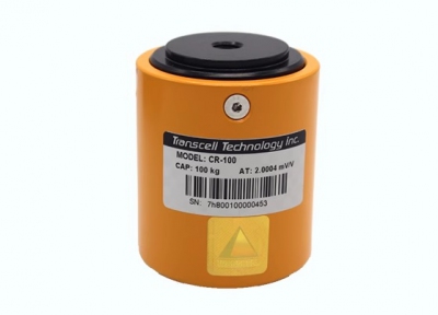
- Cảm biến tải, cảm biến cân, load cell Transcell weighing sensor CR-50KG/100KG/200KG/250KG/500KG Liên hệ
-
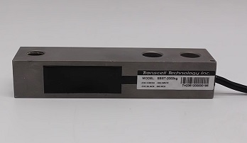
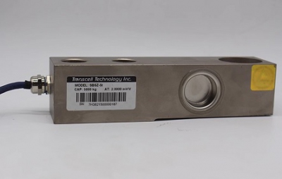
- Cảm biến tải, cảm biến cân, load cell Transcell weighing sensor SBST-200KG 500KG 1000KG 2000KG 2T Liên hệ
-
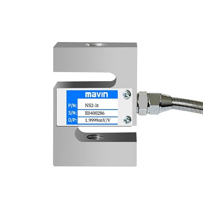
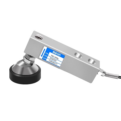
- Cảm biến tải loadcell MAVIN NS1 NS2 NS4 NS5 50kg 100kg 200kg 300kg 500kg 750kg 1t 1.5t 2t 2.5t 3t 5t Liên hệ
-
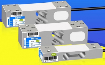
- Cảm biến tải loadcell MAVIN NA2/NA3/NA4 load sensor high-precision pressure module balance table scale sensor Liên hệ
-
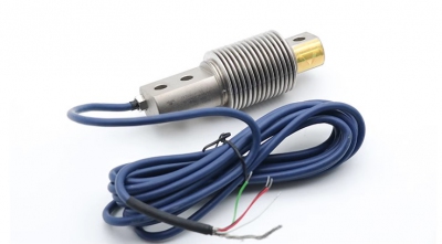
- Cảm biến tải, cảm biến cân, load cell Transcell BSH 10KG 20KG 30KG 40KG 50KG 75KG 100KG 150KG 200KG 300KG 250KG 500KG Liên hệ
TÂN THÀNH CAM KẾT
- Sản phẩm, hàng hóa chính hãng.
- Giá cả cạnh tranh.
- Dịch vụ chăm sóc khách hàng tận tâm.
Thông Tin Công Ty
Chính sách và quy định
Hỗ trợ khách hàng
THÔNG TIN LIÊN HỆ:
-------------------------------
CÔNG TY TNHH THIẾT BỊ CÔNG NGHIỆP TTH
Trụ sở: số 124 ngõ 79 Yên Hoà-Cầu giấy-HN
Kinh doanh 1 : 0816.861.515
Kinh doanh 2 : 0836.861.515
Email: tthkinhdoanh@gmail.com
Email: tthkinhdoanh01@gmail.com

