- Bộ lập trình PLC, cáp lập trình
- Màn hình HMI
- Cảm biến, phụ kiện
- Biến tần, khởi động mềm
- Máy cắt, Aptomat, khởi động từ
- Thiết bị đo lường, bảo vệ
- Thiết bị công nghiệp, tự động hóa
- Thủy lực, khí nén, van công nghiệp
- Motor, Servo motor, Servo Amplifier
- Thyristor, Module, SCR, SSR, Diode
- Phụ kiện tủ điện và vỏ tủ điện
- Cáp điện, ống bảo vệ cáp
- Thiết bị điện trung thế, truyền tải
- Thiết bị chống sét, kim thu sét
- Dụng cụ cầm tay, dụng cụ tool
- ATS, UPS, tụ bù, cuộn kháng
-
Thiết bị ngành xi măng, thép, nhiệt điện
-
Thiết bị vật tư điện nhẹ-viễn thông
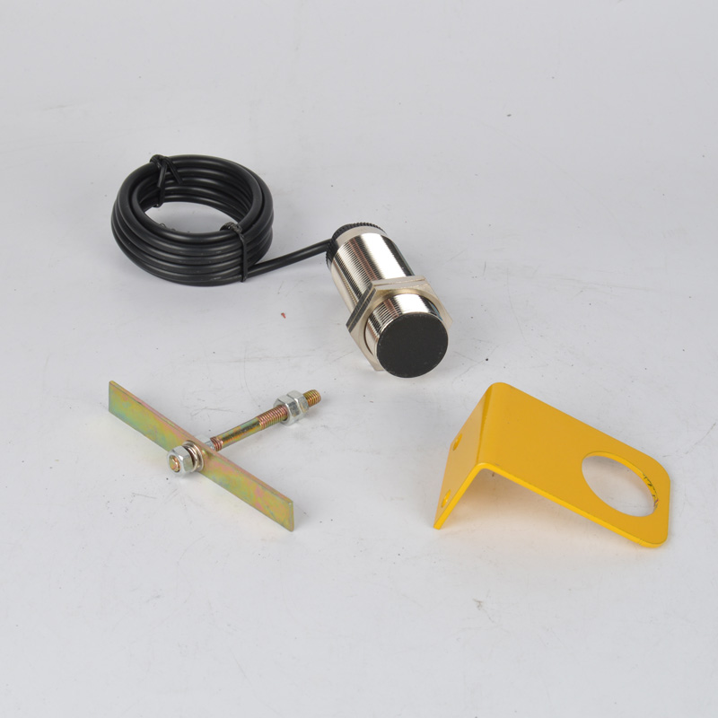
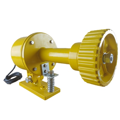
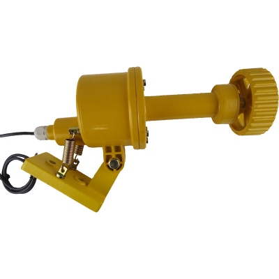
Công tắc tốc độ băng tải, Slip detector DH-RD-II ,RD-I RD-II RD-DH-III
- Overview:
The rotation detector is developed by combining the advanced technology of Schneider sensors and the practical application of domestic speed sensors ( also known as speed sensors, low speed switches, speed switches, slip switches ) . This product is mainly used in belt conveyors, hoists, screw conveyors, grinders, crushers, pumps, centrifugal dryers, mixers and dust collectors, and other rotating equipment, such as belt slippage, belt breakage, jamming, slow rotation, Mechanical failures such as shearing and overloading of the moving shaft and falling of the transmission chain ( belt ) can be handled in time to protect the equipment and reduce losses.
Tình trạng sản phẩm:
-
Working principle :
The main difference between a rotary detector and a proximity switch is that it has a delay circuit inside. It can be different from a passive axis. The main difference between a rotary detector and a proximity switch is that it has a delay circuit. It can adjust the internal speed according to the different speeds of the passive axis. The delay time is reached to protect the equipment from jamming. The rotation detector is installed on the passive shaft. As shown in Figure 1, he uses the detection piece installed on the driven shaft to use the principle of electromagnetic induction to give a speed switch pulse signal (when the detection piece It is a pulse when turning to a distance of 4-8 millimeters from the speed switch . Take Figure 1 as an example: when the power is turned on, the speed switch makes the relay pull-in delay for a set number of seconds through a series of relays. The passive axis of the device rotates once Need to give two pulses to the speed switch. If the speed switch is set to 8 seconds, the device rotates one revolution for less than 8 seconds, the speed switch does not operate through the serially connected relays (relays stay on), and when the device rotates for more than 8 seconds, The speed switch believes that a stall has occurred. The relay is tripped ( relay de-energized ) through a series of relays to protect the equipment.
Features:
● Non-contact, no moving parts, no wear, long safety life, low maintenance costs, suitable for harsh environments.
● Integrated structure, no setup, no debugging, easy installation.
● Small size, light weight and long life
● With load short-circuit protection function - connecting the rotary detector to the power supply by mistake will not damage the rotary detector. ( Not more than 1 minute )
● The output signal can be used in interlocking with field equipment or sent to the DCS control system
● Equipped with status indicator. When the device is running normally, the indicator light is “blinking”; when the device is stopped, the indicator light is “always on”.
Technical Specifications:Working power: 220VAC ± 15% Load current: ≤ 5A Insulation resistance: >500M Ω Output signal: digital signal Ambient temperature: -20 ℃ ~ + 60 ℃ Ambient humidity: ≤ 90% Dimensions: Φ 38 * 80mm Weight: 0.5kg Protection class: IP66 Detection speed range: from 1 to 1600 revolutions / min Breakout time: 3 ~ 18 seconds Response time: < 2mS Detection distance H2 : ≤ 8mm Minimum safe working distance H1 : ≥ 20mm
Installation Notes:
All transmission devices, such as screw conveyors, elevators, belt conveyors, zippers, crushers, etc., should be installed at the driven shaft ( end of the machine ) .
Note: The installation position of the rotation speed monitor in the installation diagram depends on the specific situation. You don't need to stick to this figure. As long as it does not affect the normal work, you only need to meet the condition of "pulse signals uniformly spaced to the probe within a unit time." .
Mechanical installation process:
1. Remove the end cover, drill ≥ Φ 12 holes in the center of the end cover, drill Φ 5.1 holes in the bottom of the end cover , tap M6 ( matching processing with the two holes of the rotation speed monitor bracket ) , and fix the end cover and bracket with screws
2. Drill Φ 5.1 hole in the shaft head , tap M6 , 10 ~ 15mm deep
3. Tighten the double-headed screw
4 , install the end cap
5. Install the test piece, F ≥ 20mm and fix it with nuts
6. Install a rotation speed monitor and adjust G = 4mm. Some machines have longer driven shafts and extend beyond the end cover. For such cases, you only need to make the test piece into a round shape and fix it on the shaft head ( please note The plane of the test piece is kept parallel to the plane of the probe of the rotation speed monitor. If it is installed on a metal base, in order to prevent the equipment from starting due to strong interference of magnetic materials, please pay special attention to the distance of F ) .
Electrical wiring: RT type rotation speed monitor and intermediate relay are used in series (see electrical wiring diagram). The intermediate relay coil withstands 220V .
Test piece: The material is ordinary iron sheet, the number of leaves is 2 leaves, and the size of the test piece is 100 × 10 × 2mm .
Reference formula for trip time: T (trip time)> [ 60 seconds × 3 (constant value)] ÷ [number of detected pieces × number of driven revolutions]
Wiring:


-
- Cảm biến tốc độ băng tải, công tắc tốc độ băng tải, công tắc báo trượt băng tải, Slip switch, Speed switch DH-SA,DH-T-S,DH-S, DH-X Liên hệ
-
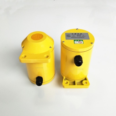
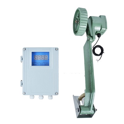
- Cảm biến tốc độ băng tải, công tắc tốc độ + hiển thị tốc độ băng tải, PLR60-23P 60-23P-X 60-23A/P type underspeed switch monitoring belt running speed Liên hệ
-
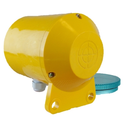
- Cảm biến tốc độ băng tải, công tắc tốc độ băng tải, công tắc báo trượt băng tải, underspeed slip switch QS-60-23P Liên hệ
-
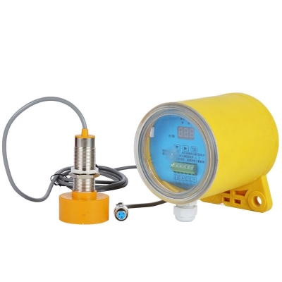
- Cảm biến tốc độ băng tải, công tắc tốc độ băng tải, công tắc báo trượt băng tải, underspeed slip switch QS-II Liên hệ
-
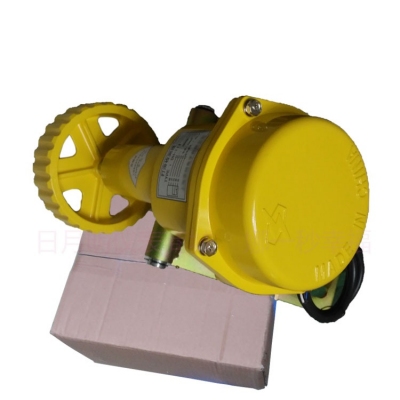
- Công tắc tốc độ băng tải, công tắc báo trượt băng tải, Slip switch, Speed switch DH-III DH-3 Liên hệ
TÂN THÀNH CAM KẾT
- Sản phẩm, hàng hóa chính hãng.
- Giá cả cạnh tranh.
- Dịch vụ chăm sóc khách hàng tận tâm.
Thông Tin Công Ty
Chính sách và quy định
Hỗ trợ khách hàng
THÔNG TIN LIÊN HỆ:
-------------------------------
CÔNG TY TNHH THIẾT BỊ CÔNG NGHIỆP TTH
Trụ sở: số 124 ngõ 79 Yên Hoà-Cầu giấy-HN
Kinh doanh 1 : 0816.861.515
Kinh doanh 2 : 0836.861.515
Email: tthkinhdoanh@gmail.com
Email: tthkinhdoanh01@gmail.com

