- Bộ lập trình PLC, cáp lập trình
- Màn hình HMI
- Cảm biến, phụ kiện
- Biến tần, khởi động mềm
- Máy cắt, Aptomat, khởi động từ
- Thiết bị đo lường, bảo vệ
- Thiết bị công nghiệp, tự động hóa
- Thủy lực, khí nén, van công nghiệp
- Motor, Servo motor, Servo Amplifier
- Thyristor, Module, SCR, SSR, Diode
- Phụ kiện tủ điện và vỏ tủ điện
- Cáp điện, ống bảo vệ cáp
- Thiết bị điện trung thế, truyền tải
- Thiết bị chống sét, kim thu sét
- Dụng cụ cầm tay, dụng cụ tool
- ATS, UPS, tụ bù, cuộn kháng
-
Thiết bị ngành xi măng, thép, nhiệt điện
-
Thiết bị vật tư điện nhẹ-viễn thông
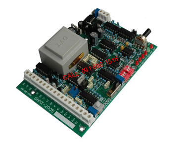
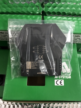
Mạch điều khiển van GAMX-2007, Actuator Control Board, Bernard Control Board GAMX-2007
Mạch điều khiển van GAMX-2007, Actuator Control Board, Bernard Control Board GAMX-2007
Tình trạng sản phẩm:
GAMX-2007 Bernard Electric Actuator
Position locator isolation module instruction manual
First, the main technical parameters
1, input signal: 4-20mA 2, input resistance 250 ohms
3, the output signal: 4-20mA, the input signal and the output signal are isolated, the user does not need to isolate the module
4, output resistance: 0-500 ohms (special need 0-750 ohms)
5. Feedback potentiometer: 0-1K ohm 6. Basic error: ±1%
7, dead zone: 0-3% adjustable 8, power supply voltage: 220V ± 10%
9, ambient temperature: -25 ° C - +55 ° C 10, relative humidity: ≤ 90% (no condensation)
Second, the main function
1. Operation mode: Forward: 4 mA valve is closed, 20 mA valve is open Reverse: 4 mA valve is open, 20 mA valve is closed.
2. Interrupt hold: When the signal is lost, the actuator can remain in the home position, closed or open, and the interrupt signal setting actuator remains in the home position at the factory.
3. Manual operation of the machine: The manual operation of the machine is to make the positioner simulate a 4-20 mA input signal, so that the actuator can be manually adjusted to fully open or close.
4, 0% position: positioner 0%, so that the actuator is fully closed.
5, 100% position: the positioner is 100%, so that the actuator is fully open.
6. When the terminals 19 and 34 are shorted , the automatic control is turned off, and the manual is turned into the short circuit. The terminals 34 and 35 are manually turned off, and the short terminals 34 and 36 are manually opened. Remote control takes precedence over automatic control. When the controller is in the remote control position, the automatic control is blocked and does not work. The remote control is jog.
7, actuator running direction:
In standard form : the actuator (for the output shaft) is turned clockwise
The DIP switch can be used to change the control (change the direction of motor rotation) to turn the actuator counterclockwise and change the direction of the limit switch and torque switch.
8, electric brake configuration: GAMX-2005 module 220VAC and 380VAC universal
Single phase power supply ( 220VAC) with electric brake
The three-phase power supply ( 380VAC) makes the electric brake function ineffective through the dial switch, and the actuator electric brake is completed by the external circuit.
9, LED instructions:
LED1 ( red) power indicator LED 2 (green) actuator on LED3 (red) actuator off
LED4 (red) loses 4-20mA signal LED5 (red) over torque switch
LED6 (red) electric brake works, the brake light flashes instantly
10.
11,
12, P1 : adjust P1 clockwise to adjust the valve to close, counterclockwise to open the valve, at this time COMV must be in theMAN position
13, P2 : 100 % full scale adjustment. Adjust the feedback current clockwise to increase, at this time COMV is in the AUTOposition.
14, P3 : dead zone adjustment reference value: clockwise adjustment P3 , dead zone increase, low sensitivity, counterclockwise adjustment P3 dead zone reduction, high sensitivity, actuator in the automatic adjustment state, adjust the P3 potentiometer to make the actuator The best state is when the vibration is not oscillated and the highest sensitivity is reached. At this time, theCOMV is in the AUTO position.
15,
Third, the debugging method:
The actuator works in the machine to automatically adjust the working state, use the remote control terminals 34 , 35 , 36 to fully close the actuator, adjust the position potentiometer, make the feedback current 4mA , make the actuator fully open, adjust the full potentiometer P2 makes the feedback current 20mA , repeat the above operation several times, until the actuator is fully closed corresponding to the feedback current 4mA , fully open corresponding to the feedback current 20mA .
-
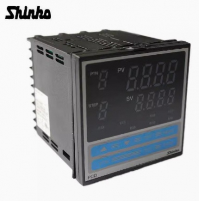
- Bộ điều khiển nhiệt độ JCD-33A-A/M JCD-33A-A/M BK JCD-33A-R/M BK A2 C5 JCD-33A-R/M BK C5 JCD-33A-S/M JCD-33A-S/M BK C5 JCD-33A-S/M A2 JCD-33A-S/M BK DS Liên hệ
-
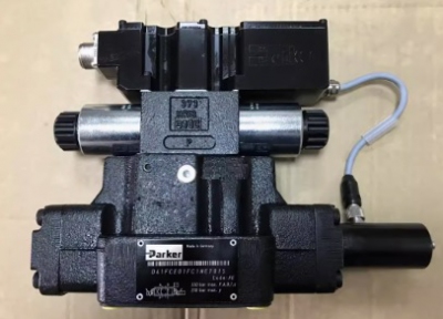
- Van tỷ lệ Parker proportional valve D41FCB31FC1NE70 D41FCE01FC1NE70 D41FBE01FC1NF00 D41FBE01FC4NF00 Liên hệ
-
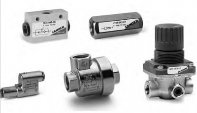
- Van kiểm tra Camozzi check valve VNR-210-1/8 VNR-205-M5 VNR-843-07 VNR-238-3/8 VNR-212-1/2 VNR-234-3/4 VNR-201-1 Liên hệ
-

- Đồng hồ Shihlin WT409-10100002AS WT409-20100002AS WT409-30100002AS WTH49-10100002AS WTH49-20100002AS WTH49-30100002AS Liên hệ
-

- Bộ điều khiển tốc độ quạt ALCO Emerson fan speed regulator pressure sensor FSO-N15 FSY-42S FSY-43S FSO-N30 Liên hệ
-

- Công tắc áp suất pressure switch SG307-F-150 ST307-350-B SG307-F-350 SG307-F-55 ST307-150-B SG307-F-V2-150 ST307-SCH-V2-350-B ST307-V2-350-B SG307- F-V2-55 SG307-F-150-B Liên hệ
TÂN THÀNH CAM KẾT
- Sản phẩm, hàng hóa chính hãng.
- Giá cả cạnh tranh.
- Dịch vụ chăm sóc khách hàng tận tâm.
Thông Tin Công Ty
Chính sách và quy định
Hỗ trợ khách hàng
THÔNG TIN LIÊN HỆ:
-------------------------------
CÔNG TY TNHH THIẾT BỊ CÔNG NGHIỆP TTH
Trụ sở: số 124 ngõ 79 Yên Hoà-Cầu giấy-HN
Kinh doanh 1 : 0816.861.515
Kinh doanh 2 : 0836.861.515
Email: tthkinhdoanh@gmail.com
Email: tthkinhdoanh01@gmail.com

