- Bộ lập trình PLC, cáp lập trình
- Màn hình HMI
- Cảm biến, phụ kiện
- Biến tần, khởi động mềm
- Máy cắt, Aptomat, khởi động từ
- Thiết bị đo lường, bảo vệ
- Thiết bị công nghiệp, tự động hóa
- Thủy lực, khí nén, van công nghiệp
- Motor, Servo motor, Servo Amplifier
- Thyristor, Module, SCR, SSR, Diode
- Phụ kiện tủ điện và vỏ tủ điện
- Cáp điện, ống bảo vệ cáp
- Thiết bị điện trung thế, truyền tải
- Thiết bị chống sét, kim thu sét
- Dụng cụ cầm tay, dụng cụ tool
- ATS, UPS, tụ bù, cuộn kháng
-
Thiết bị ngành xi măng, thép, nhiệt điện
-
Thiết bị vật tư điện nhẹ-viễn thông
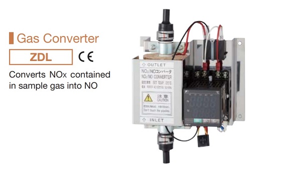
Bộ chuyển đổi khí ZDL03 NO2/ NO gas converter trong phân tích khí Fuji
Mã Sản phẩm : ZDL03
Chuyên mục : Gas Converter
Nhà sản xuất : Fuji Electric
Hàng sẵn kho : 01
Mô tả:
The N02/N0 converter is to be coupled with a NOx gas analyzer or NH3 gas analyzer for flue exhaust. It is converter using a special catalyst which efficiently converts N02 in sample gas to NO.
Chuyên mục : Gas Converter
Nhà sản xuất : Fuji Electric
Hàng sẵn kho : 01
Mô tả:
The N02/N0 converter is to be coupled with a NOx gas analyzer or NH3 gas analyzer for flue exhaust. It is converter using a special catalyst which efficiently converts N02 in sample gas to NO.
Tình trạng sản phẩm:
Thông số chi tiết :
This gas converter is composed of the converter block and the temperature regulator block.
3. Installation, Piping, Wiring
(1) The main frame should be installed vertically to the ground. Avoid installing it obliquely or laying it on its side. Be careful not to apply load to the joints at the top and the bottom.
(2) Pipes should be connected so that the bottom port of converter block becomes an inlet and the top port becomes an outlet. (Refer to “3. Outline Drawing.”)
(3) Connect power supply to the terminals indicated in the wiring diagram. (Use type D for grounding.)
(4) Install fuse or power switch separately.
(5) Confirm the piping and wiring before turning ON the converter.
(6) Be careful of the high temperature after turning the power on. The temperature regulator ([*]) is set at 220°C. Since temperature has been factory-set, the temperature regulator need not be operated.
(b) Under SV (Set Value) display, set 220°C by pressing the [A] or 0 key and determine it by the
I ENT | key. (200°C need be set for NO/CO analyzer.)
(c) Run automatic tuning when temperature is unstable.
(d) The temperature controller controls converter temperature through the SSR relay.
4. How to Replace Catalyst
During catalyst replacement, carefully protect your body from a burn because the converter block is hot.
Catalyst and filter should be replaced with new ones once
every eight months, (when flow rate is 0.5L/min or lower
and NO2 concentration is 10 ppm or lower)
(1) Turn off the main power supply for converter.
(2) When it has cooled down, remove One touch band from the upper joint (1) shown in Fig. 2 with a pair of pliers or other apparatus. The lower joint (1) can be easily removed by shifting it gradually with a blade-edge screwdriver. Attention should be paid not to damage the ceramic heater.
(3) Pull out the metal fitting plates (2).
[CAUTION] Place a catch pan or sort to receive the falling catalyst (3) and glass wools (4).
(4) Place (4) at the end of metal fitting plate (long) (2), insert it from the lower side of the ceramic heater, then inject the new (3) from the top, using a funnel or alike.
(5) Attach new joints (1) and (5) to the heater and reconnect it to piping, then fasten all the straps of the bands. Turn ON the power supply.
(a) When pressing the | PV/SV | key, display changes over between PV and SV. Variable) display is set.)
Setting of temperature controller for NO2/NO converter (PXZ4TCY2-0Y100).
6. Scope of Delivery
(1) Main unit
(2) N02/N0 catalyst (already set into the main unit)
(3) Glass wool (already set into the main unit)
7. Spare Parts for One Year
1. ZBN1DL72
N02 5ppm or lower (0.5L/min flow late)
NO2 lOppm or lower (0.3L/min flow late)
2. ZBN1DL82
NO2 lOppm or lower (0.5L/min flow late)
8. Compatible Standards
JISB7982 Automatic measuring instrument for nitrogen oxides in exhaust gas
- Catalyst : Carbon, replacement required every 8 months (when N02 concentration is 10 ppm or lower)
- Gas flow rate : About 0.5L/min.
- Set temperature : 220±10°C
- Thermocouple : K
- Power supply :100V AC, 50/60Hz
- Power consumption : About 85VA
- Material of parts fhat contact gas : Ceramic, Viton, Glass wool, SUS316
- Gas inlet/outlet connection method : Insert Teflon tube ⱷ6 mm/ⱷ4 mm into Viton connection port of inner diameter ⱷ5.5 mm. (Withstand pressure: l0 kPa)
This gas converter is composed of the converter block and the temperature regulator block.
3. Installation, Piping, Wiring
(1) The main frame should be installed vertically to the ground. Avoid installing it obliquely or laying it on its side. Be careful not to apply load to the joints at the top and the bottom.
(2) Pipes should be connected so that the bottom port of converter block becomes an inlet and the top port becomes an outlet. (Refer to “3. Outline Drawing.”)
(3) Connect power supply to the terminals indicated in the wiring diagram. (Use type D for grounding.)
(4) Install fuse or power switch separately.
(5) Confirm the piping and wiring before turning ON the converter.
(6) Be careful of the high temperature after turning the power on. The temperature regulator ([*]) is set at 220°C. Since temperature has been factory-set, the temperature regulator need not be operated.
(b) Under SV (Set Value) display, set 220°C by pressing the [A] or 0 key and determine it by the
I ENT | key. (200°C need be set for NO/CO analyzer.)
(c) Run automatic tuning when temperature is unstable.
(d) The temperature controller controls converter temperature through the SSR relay.
4. How to Replace Catalyst
During catalyst replacement, carefully protect your body from a burn because the converter block is hot.
Catalyst and filter should be replaced with new ones once
every eight months, (when flow rate is 0.5L/min or lower
and NO2 concentration is 10 ppm or lower)
(1) Turn off the main power supply for converter.
(2) When it has cooled down, remove One touch band from the upper joint (1) shown in Fig. 2 with a pair of pliers or other apparatus. The lower joint (1) can be easily removed by shifting it gradually with a blade-edge screwdriver. Attention should be paid not to damage the ceramic heater.
(3) Pull out the metal fitting plates (2).
[CAUTION] Place a catch pan or sort to receive the falling catalyst (3) and glass wools (4).
(4) Place (4) at the end of metal fitting plate (long) (2), insert it from the lower side of the ceramic heater, then inject the new (3) from the top, using a funnel or alike.
(5) Attach new joints (1) and (5) to the heater and reconnect it to piping, then fasten all the straps of the bands. Turn ON the power supply.
(a) When pressing the | PV/SV | key, display changes over between PV and SV. Variable) display is set.)
Setting of temperature controller for NO2/NO converter (PXZ4TCY2-0Y100).
6. Scope of Delivery
(1) Main unit
(2) N02/N0 catalyst (already set into the main unit)
(3) Glass wool (already set into the main unit)
7. Spare Parts for One Year
1. ZBN1DL72
N02 5ppm or lower (0.5L/min flow late)
NO2 lOppm or lower (0.3L/min flow late)
2. ZBN1DL82
NO2 lOppm or lower (0.5L/min flow late)
| Spare parts Type | ZBN1DL72 | ZBN1DL82 |
| N02/N0 catalyst (TK726891C1) | 1 | 2 |
| Glass wool (TK726890C1) (0.3 to 0.5g) | 1 | 2 |
| Joint (TK7G6890P1) | 2 | 4 |
8. Compatible Standards
JISB7982 Automatic measuring instrument for nitrogen oxides in exhaust gas
-
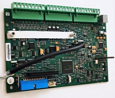
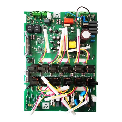
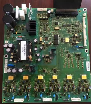
- Mạch điều khiển Parker 590PCPU board control motherboard control card AH470372U002 AH500075U002 Liên hệ
-
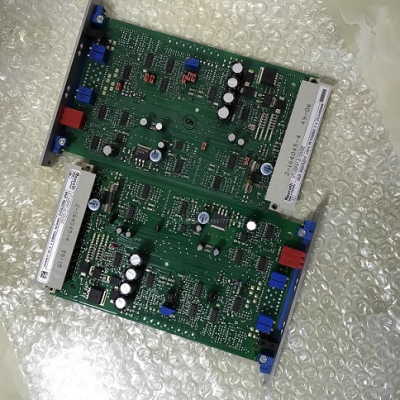
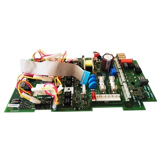
- Mạch Khuếch đại R900579497 VT5035-1X R901236404 VT5041-31/1-0 R901196678 VT5041-3X/3-0 R900033823 VT-VSPA1-1-11 R900021909 VT-VSPA2-1-11/T1 R900214081 VT-VSPA2-50-10/T1 Liên hệ
-

- Bộ điều khiển nhiệt độ Delixi intelligent digital display temperature controller XMT-101/102/121/122 K/E/PT100/CU50 temperature controller Liên hệ
TÂN THÀNH CAM KẾT
- Sản phẩm, hàng hóa chính hãng.
- Giá cả cạnh tranh.
- Dịch vụ chăm sóc khách hàng tận tâm.
Thông Tin Công Ty
Chính sách và quy định
Hỗ trợ khách hàng
THÔNG TIN LIÊN HỆ:
-------------------------------
CÔNG TY TNHH THIẾT BỊ CÔNG NGHIỆP TTH
Trụ sở: số 124 ngõ 79 Yên Hoà-Cầu giấy-HN
Kinh doanh 1 : 0816.861.515
Kinh doanh 2 : 0836.861.515
Email: tthkinhdoanh@gmail.com
Email: tthkinhdoanh01@gmail.com

