- Bộ lập trình PLC, cáp lập trình
- Màn hình HMI
- Cảm biến, phụ kiện
- Biến tần, khởi động mềm
- Máy cắt, Aptomat, khởi động từ
- Thiết bị đo lường, bảo vệ
- Thiết bị công nghiệp, tự động hóa
- Thủy lực, khí nén, van công nghiệp
- Motor, Servo motor, Servo Amplifier
- Thyristor, Module, SCR, SSR, Diode
- Phụ kiện tủ điện và vỏ tủ điện
- Cáp điện, ống bảo vệ cáp
- Thiết bị điện trung thế, truyền tải
- Thiết bị chống sét, kim thu sét
- Dụng cụ cầm tay, dụng cụ tool
- ATS, UPS, tụ bù, cuộn kháng
-
Thiết bị ngành xi măng, thép, nhiệt điện
-
Thiết bị vật tư điện nhẹ-viễn thông
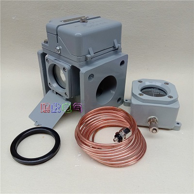
Rơ le hơi, Gas relay, Gas relay QJ3-80A-TH
- QJ1-50 gas relay pipeline diameter φ50
QJ1-80 gas relay pipeline diameter φ80
QJ4-25 gas relay pipeline diameter φ25
QJ4-50 gas relay Pipe diameter φ50
QJ4-80 gas relay pipeline diameter φ80
Tình trạng sản phẩm:
1.1 The main purpose of the product
Gas relay is a protection device used in oil-immersed transformers and oil-immersed on-load tap-changers. The gas relay (hereinafter referred to as the relay) is installed on the joint pipe of the transformer tank cover and the oil storage tank. When the internal fault of the transformer causes the oil to decompose to generate gas or cause the oil flow to impulse, the contact of the gas relay is activated to connect the specified Control circuit and send out signal in time or automatically cut off
1.2 varieties and specifications of transformer
QJ1-50 gas relay pipeline diameter φ50
QJ1-80 gas relay pipeline diameter φ80
QJ4-25 gas relay pipeline diameter φ25
QJ4-50 gas relay Pipe diameter φ50
QJ4-80 gas relay pipeline diameter φ80
1.3 Model composition and its representative significance
Note: 1 ) The special use environment code is
TH— wet tropical type; TA— dry tropical type; general type is not indicated.
2 ) Those marked with G on the back of the model are improved products, namely QJ4 products.
1.4 Conditions
1.4.1 allowable working temperature: -30 ~ + 95 deg.] C .
1.4.2 Installation method: The axis of the relay pipeline should be parallel to the transformer tank cover, and the end leading to the oil storage tank is allowed to be slightly higher, but the inclination of the axis to the horizontal plane does not exceed 4% .
2 Structure and working principle
2.1 Structure of gas relay
QJ type relay structure is basically the same, except that QJ4-25 type trip signal is single contact type, the others are double contact type. The structure of the relay core is shown in Figure 1. The upper part of the relay core consists of an open cup (float) 3 , a weight 4 , a magnet 6, and a reed contact 10.The gas volume device constituting the signal is composed of a baffle 5 , a spring 8 , an adjustment lever 9 , a magnet 6 and a reed contact 10 which constitute a flow rate device which operates in a trip. The covered gas plug 1 is used for exhausting during installation and for extracting faulty gas during operation. Probe 2 is used to check the flexibility and reliability of the trip mechanism.
Figure 1 Relay core structure
1 Air plug 2 Probe 3 Open cup (float) 4 Heavy hammer 5 Baffle
6 Magnet 7 Terminal 8 Spring 9 Adjusting rod 10 Reed contact
2.2 Working principle of gas relay
The relay is normally filled with transformer oil during normal operation, and the open cup (float) is in the upturned position shown in Figure 1 . When there is a slight fault inside the transformer, the gas generated by the transformer oil due to the decomposition is collected in the gas chamber on the upper part of the relay, forcing the oil level to drop, and the opening cup 3 is lowered to a certain position. The magnet 6 on it makes the reed contact 10 Pull in, connect the signal loop, and send out an alarm signal. If the oil level in the fuel tank drops, it also acts on the signal circuit and sends out an alarm signal. When a serious failure occurs inside the transformer, the pressure in the fuel tank rises instantaneously, and an oil surge will occur. The baffle 5 will be impulsive . When the baffle rotates to a limited position, the magnet 6 on the baffle will attract the reed contact 10 Close the trip circuit and directly cut off the power supply of the transformer without warning, so as to protect the transformer.
3 main technical parameters
Table 1 Specification Model line Diameter
mm Number of gas accumulation
mL Oil speed setting range
m / s contact capacity Note
QJ1-50 50 250 ~ 300 0.6 ~ 1.2
AC direct stream 220V
electrical flow
0.3A
QJ1-80 80 250 ~ 300 0.7 ~1.5
QJ4-25 25 or less 1.0
QJ4-50 50 250 ~300 0.6 ~1.2 instead of QJ1G-50
QJ4-80 80 250 ~300 0.7 ~1.5 instead of QJ1G-80
Table 2 Product model D0 HLDA d BMass kg
QJ1-50 φ50 220 160 φ130 120 M12 100 10.3
QJ1-80 φ80 220 160 φ130 120 M12 100 9.3
QJ4-50 φ50 215 185 φ125 125 φ14 100 11.1
QJ4-80 φ80 235 185 φ160 160 φ18 100 13.35
Note: with The jointed gas relay (commonly known as type A product) is used together with the air extraction box, and requirements should be made when ordering, otherwise it is generally not equipped with a joint.
5 Installation and commissioning
5.1 Installation of the relay
5.1.1 Newly manufactured relays must be removed from the relay core before installation and use, and the binding straps for transportation and fixing must be removed. And check whether all the fasteners are loose, whether the opening cup (float) and the baffle are flexible, and whether the contacts are reliably opened and closed.
5.1.2 The relay should be installed on the joint pipe between the oil tank of the oil-immersed transformer and the oil storage tank. The inner diameter of the joint pipe should be the same as the pipeline diameter (caliber) of the relay. The arrow on the relay must point to the oil storage tank. . The end of the oil storage tank is allowed to be slightly higher, but the inclination of the axis of the union and the horizontal plane must not exceed 4% , or the method of installing an inclined gas connection pipe is used to allow the gas inside the transformer to enter the relay smoothly.
5.1.3 In order to facilitate the maintenance of the gas relay at the operation site, its installation position should ensure that the relay core can be smoothly removed from the casing. QJ4-25 type take out height is 130mm , QJ-50、80 type take out height is 150mm .
5.2 Commissioning
The gas relay is an important protection device for oil-immersed transformers, so the operating department has special regulations. For example, it must be commissioned, inspected and issued by the inspection department before it can be put into use. Therefore, commissioning and oil speed setting should be performed in accordance with relevant regulations.
5.2.1 Adjustment of gas volume
Changing the position of the reed contact can adjust the gas volume of the signal contact. The amount of gas volume decreases when the reed contact moves up, and the amount of gas increases when the reed contact moves down. Tighten the locking screws after adjustment.
5.2.2 Oil speed adjustment
Adjusting the adjustment lever connected to the spring can change the tension of the baffle spring, which can change the oil speed of the trip contact action (the relay has been set when it leaves the factory, see the certificate for its value), and the nut should be locked after adjustment. The setting of the working oil speed should be performed by a professional on a dedicated flow rate calibration device.
5.2.3 Baffle rotation angle adjustment
Adjusting the stop screw can change the rotation angle of the baffle, that is, the distance between the magnet and the reed contact ( 0.5 to 1.0mm ) can be adjusted to ensure that the reed contact is opened and closed reliably.
6 Maintenance and repair
6.1 The relay should be inspected once a year for appearance inspection, signal circuit reliability and trip circuit reliability inspection.
6.2 The relays that have been operated should be opened every two years to check the internal structure and operational reliability.
6.3 The relays in operation shall be subjected to a power frequency withstand voltage test every five years.
-
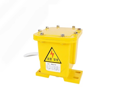
- Công tắc báo rách băng tải ZLK-1 automatic tear switch belt tear switch ZL-II longitudinal tear detector DB-100 Liên hệ
-
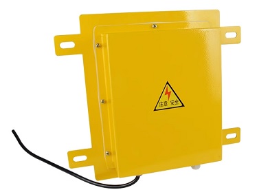
- Công tắc báo tắc phễu bồn bin KBW220 coal blockage switch LDM-Y explosion-proof chute blockage switch DS-I Liên hệ
-
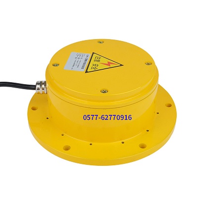
- Công tắc báo tắc phễu bồn bin LDM-X round chute clogging switch DS-I chute clogging detector KBW220 clogging switch XLDS-I Liên hệ
-
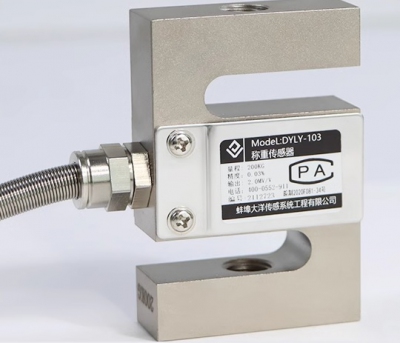
- Cảm biến trọng lượng pressure weighing load cell DYLY-103 batching scale 5kg 10kg 20kg 30kg 50kg 100kg 200kg 300kg 500kg 1000kg 1500kg 2000kg 3000kg 5000kg Liên hệ
-
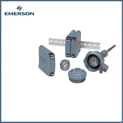
- Bộ chuyển đổi tín hiệu nhiệt độ Rosemount Temperature Transmitter 248HANANONS 248HANAU1NS 248RANA 248HAK5A2NS 248HAE1U2NS 248HANAN0C4Q4 248HAI5U2NS Liên hệ
-

- Camera công nghiệp Hikvision Industrial Camera MV-CS050-10GM/GC 5 million black and white/color 2/3" Gigabit Ethernet Liên hệ
TÂN THÀNH CAM KẾT
- Sản phẩm, hàng hóa chính hãng.
- Giá cả cạnh tranh.
- Dịch vụ chăm sóc khách hàng tận tâm.
Thông Tin Công Ty
Chính sách và quy định
Hỗ trợ khách hàng
THÔNG TIN LIÊN HỆ:
-------------------------------
CÔNG TY TNHH THIẾT BỊ CÔNG NGHIỆP TTH
Trụ sở: số 124 ngõ 79 Yên Hoà-Cầu giấy-HN
Kinh doanh 1 : 0816.861.515
Kinh doanh 2 : 0836.861.515
Email: tthkinhdoanh@gmail.com
Email: tthkinhdoanh01@gmail.com


